Simple tutorial
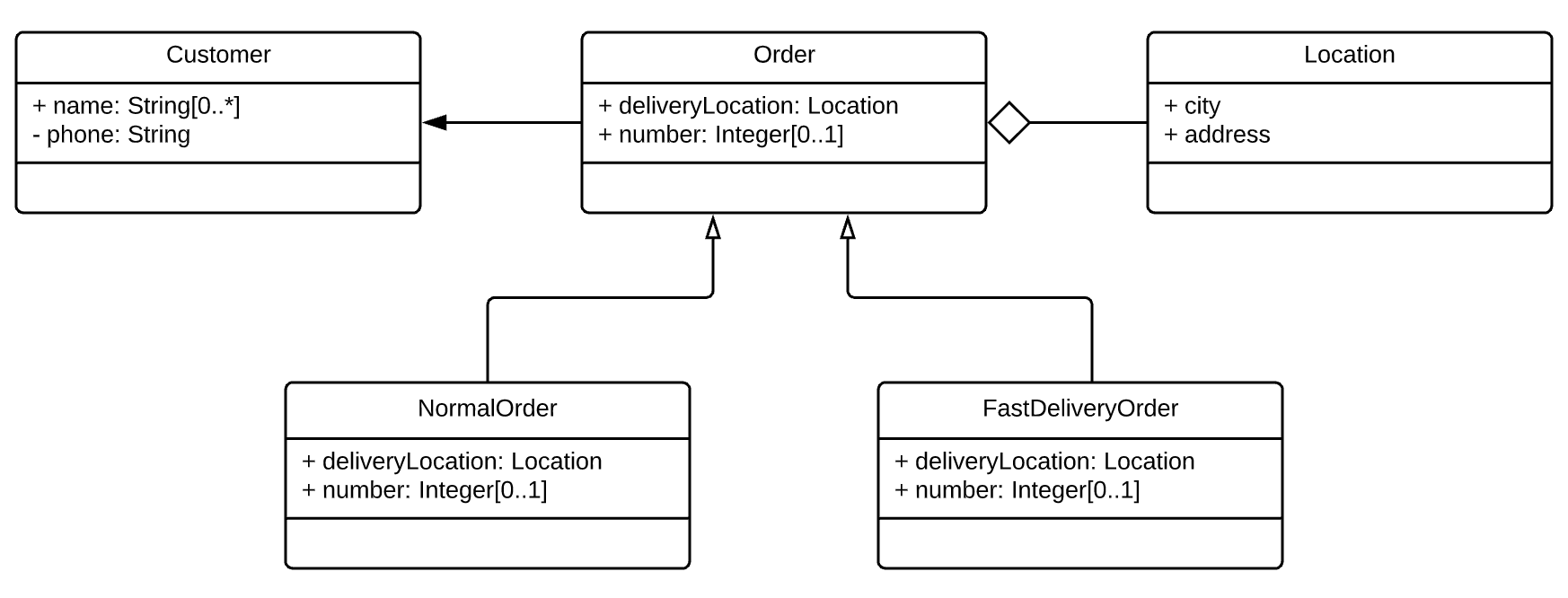
In this article we will try to create a simple lutaml uml file from the following diagram:

Plantuml version
This simple diagram can be represented as the following plantuml file:
@startuml
'******* CLASS GROUPS *************************************************

class Customer {
  +name: String[0..*]
  -phone: String
}

class Order {
  +deliveryLocation: Location
  +number: Integer[0..1]
}

class Location {
  +city
  +address
}

class NormalOrder {
  +deliveryLocation: Location
  +number: Integer[0..1]
}

class FastDeliveryOrder {
  +deliveryLocation: Location
  +number: Integer[0..1]
}

'******* CLASS RELATIONS **********************************************
Order o-- Location
NormalOrder --|> Order
FastDeliveryOrder --|> Order
Order --> Customer
@enduml
Diagram root tag
In plantuml we start our diagram definition with @startuml keyword and end with @enduml, in lutaml uml this role is given to the diagram tag:
diagram MyView {
  title "My diagram"
}
You can supply additional attributes for diagram in diagram root tag, we can set custom diagram name with title attribute or set custom font with fontname attribute.
Classes representation
Class objects can be described with class keyword, visibility of attributes can be controlled with symbols +, -, #, if no visibility modifier provided lutaml will treat attribute entity as public attribute:
class Customer {
  +name: String[0..*] // Similar visibility: `name: String`
  -phone: String
}
// is a comment tag for lutaml uml, code after this tag on this line will be ignored by parser. The code above is pretty similar to the plantuml version. Lutaml uml also supports class and attribute annotations which can be described with definition keyword. Lutaml uml parser will parse these tags and link them to the related entities(class/enum or attribute/value). Here is the example:
class Customer {
  definition { Class describing customer entity and its metadata }
  +name: String[0..*] {
    definition {
      first name of the client, in lower case
    }
  }
  -phone: String
}
The whole classes representation will look like this:
diagram MyView {
  title "my diagram"

  class Customer {
    name: String[0..*]
    -phone: String
  }

  class Order {
    deliveryLocation: Location
    number: Integer[0..1]
  }

  class Location {
    city
    address
  }

  class NormalOrder {
    deliveryLocation: Location
    number: Integer[0..1]
  }

  class FastDeliveryOrder {
    deliveryLocation: Location
    number: Integer[0..1]
  }
}
Associations representation
Unlike plantuml, lutaml uml uses here special keyword association to define associaton. Here is an example:
association {
  owner_type aggregation
  member_type direct
  owner A
  member B
}
owner and member` keywords describes direction of association, in order to describe plantuml association A —> B we need to write the following lutaml uml code:
association {
  owner A
  member B
}
owner_type and member_type describes the type of association to display, if we dont supply any type lutaml uml will use the default arrow style - inheritance. In case of our example diagram the relation between Order and NormalOrder/FastDeliveryOrder can be described with the following code:
association {
  owner NormalOrder
  member Order
}
association {
  owner FastDeliveryOrder
  member Order
}
In order to described the inheritance between Order and NormalOrder/FastDeliveryOrder we need to use member_type attribute:
association {
  member_type 'direct'
  owner Order
  member Customer
}
In order to represent aggregation relation between
association {
  member_type aggregation
  owner Location
  member Order
}
The whole associations block will look like this:
association {
  owner NormalOrder
  member Order
}

association {
  owner FastDeliveryOrder
  member Order
}

association {
  member_type 'direct'
  owner Order
  member Customer
}

association {
  member_type aggregation
  owner Location
  member Order
}
Putting it all together
The resulting lutaml file will look like this:
diagram MyView {
  title "my diagram"

  //******* CLASS GROUPS *************************************************
  class Customer {
    name: String[0..*]
    -phone: String
  }

  class Order {
    deliveryLocation: Location
    number: Integer[0..1]
  }

  class Location {
    city
    address
  }

  class NormalOrder {
    deliveryLocation: Location
    number: Integer[0..1]
  }

  class FastDeliveryOrder {
    deliveryLocation: Location
    number: Integer[0..1]
  }

  //******* CLASS RELATIONS **********************************************

  association {
    owner NormalOrder
    member Order
  }

  association {
    owner FastDeliveryOrder
    member Order
  }

  association {
    member_type 'direct'
    owner Order
    member Customer
  }

  association {
    member_type aggregation
    owner Location
    member Order
  }
}